Quick disconnects are becoming one of the most important — and least understood — interfaces in AI data-center liquid cooling.
As rack power density and coolant flow continue to increase, the industry is moving beyond the first stage of liquid-cooling standardization.
The initial challenge was straightforward: make products from different suppliers physically connect.
The next challenge is harder.
Can those connections deliver predictable flow, low pressure loss, minimal leakage, long service life and reliable interoperability across thousands of ports?
This distinction is becoming increasingly important as the Open Compute Project (OCP) liquid-cooling ecosystem expands.
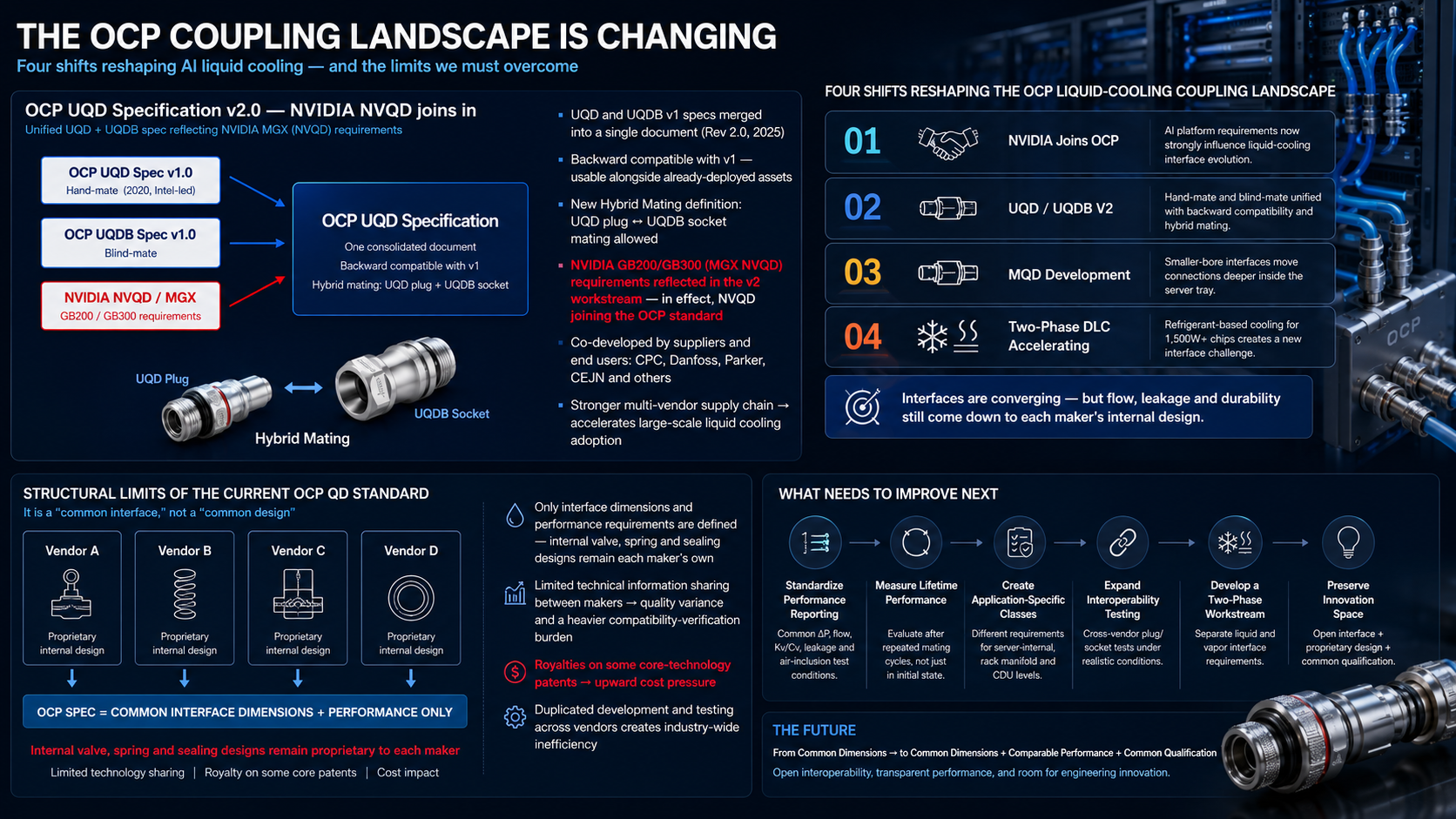
Four developments are now reshaping the coupling landscape:
- NVIDIA's growing influence on OCP liquid-cooling requirements,
- the transition toward UQD/UQDB V2,
- the emergence of smaller MQD interfaces inside server platforms,
- and the acceleration of two-phase direct liquid cooling.
Together, these changes point toward a more mature liquid-cooling ecosystem — but they also expose the structural limitations of a standard that primarily defines the interface rather than the complete internal design.
1. The Coupling Is No Longer Just a Connector
In a conventional industrial fluid system, a quick disconnect is often treated as an individual component.
AI data centers change that perspective.
A modern liquid-cooled server may contain many fluid connections across the path between the CDU, rack manifold, server tray and cold plate.
A typical cooling path can be simplified as:
CDU → Rack Manifold → Hose → QD → Server Manifold → Cold Plate → Return
Every coupling in that chain creates hydraulic resistance.
A small pressure drop across one QD may appear insignificant. But when dozens or hundreds of connections operate in parallel across a rack or data hall, the cumulative effect influences pump power, flow distribution and thermal performance.
That is why modern data-center QDs must be evaluated not only by nominal size or whether two halves can physically mate.
Important parameters increasingly include:
- flow coefficient,
- pressure drop,
- fluid displacement during connection and disconnection,
- air inclusion,
- leakage,
- connecting force,
- misalignment tolerance,
- cycle durability,
- seal compatibility,
- and manufacturing consistency.
The coupling has become part of the thermal architecture.
2. Shift One — AI Platform Vendors Are Shaping the Interface
The first major change is that liquid-cooling coupling requirements are becoming increasingly connected to AI server platform architecture.
As major AI platforms adopt liquid cooling as a standard design assumption, fluid interfaces can no longer evolve independently from server design.
GPU layout, cold-plate configuration, server-tray geometry, manifold location and service strategy all influence where a coupling must be placed and how much flow it must carry.
This makes the relationship between compute architecture and cooling interface much closer than it was in traditional data centers.
A server vendor deciding to move a manifold deeper inside the tray, for example, may create demand for a smaller coupling with lower connecting force and tighter packaging.
A rack architecture moving to blind-mate service may require greater radial and angular misalignment tolerance.
In other words:
The cooling interface is increasingly being shaped by the compute platform itself.
3. Shift Two — UQD/UQDB V2 Moves Beyond Basic Compatibility
Early OCP liquid-cooling QD standardization focused heavily on creating a common mechanical interface.
This was an important first step.
Without dimensional interoperability, every server vendor could become dependent on a proprietary fluid connection ecosystem.
UQD/UQDB V2 represents a more mature direction.
The new generation aims to bring Hand Mate and Blind Mate interfaces into a more unified specification while maintaining backward compatibility with earlier implementations.
Hybrid mating between compatible hand-mate and blind-mate components also increases flexibility across rack and server architectures.
At the same time, the industry is paying greater attention to repeated mating, leakage and practical performance verification.
This is an important evolution.
Compatibility is moving from “Can these two parts connect?” toward “Can these two parts perform predictably together?”
4. Shift Three — MQD Pushes Quick Disconnects Deeper Inside the Server
Another important development is the expansion of QDs from rack-level connections into the server itself.
Large and medium interfaces are suitable for CDU and rack-manifold connections, but server trays have much tighter space constraints.
This creates demand for smaller-bore interfaces such as MQD-type connections.
The application can move closer to the heat source:
Inner Manifold → Small-Bore QD → Cold Plate
This transition changes the engineering priorities.
Server-side QDs need to combine adequate flow with:
- very compact dimensions,
- low connecting force,
- dense installation pitch,
- minimal fluid loss,
- and repeatable assembly.
Blind-mate versions make the problem even more demanding because the coupling must compensate for manufacturing tolerances and positional error without human adjustment.
The result is a new layer of the liquid-cooling market.
QD technology is no longer limited to connecting the rack to the facility. It is moving inside the compute system.
5. Shift Four — Two-Phase DLC Creates a New Interface Problem
The fourth shift may eventually be the most disruptive.
Single-phase DLC primarily circulates water or water-glycol coolant while the fluid remains liquid.
Two-phase DLC operates differently.
A refrigerant evaporates at the heat source and carries energy through latent heat. This can provide high heat-transfer capability, particularly as chip heat flux continues to increase.
But two-phase cooling creates a very different requirement for the coupling.
The system may contain both:
Liquid refrigerant lines and vapor return lines.
These two flow conditions do not necessarily require the same geometry.
Seal compatibility, refrigerant permeation, vapor leakage, internal volume, pressure drop and extremely high tightness become more important.
Most importantly, there is currently no broadly established common OCP QD specification for two-phase DLC comparable to the mature single-phase ecosystem.
This leaves suppliers and system developers designing their own solutions.
That is both a challenge and an opportunity.
The Structural Limitation of Today's OCP QD Model
The OCP approach has created significant value by defining common interfaces.
However, a common interface should not be confused with a common internal design.
Different manufacturers can produce couplings that share compatible external dimensions while using completely different:
- valve geometries,
- spring arrangements,
- seal locations,
- flow passages,
- surface treatments,
- and manufacturing methods.
This is not necessarily a weakness. Proprietary engineering is what allows suppliers to innovate.
But it creates an important consequence:
Two couplings can be interface-compatible without being performance-equivalent.
Problem 1 — Compatibility Does Not Guarantee Equal Flow Performance
Internal geometry determines how much of the nominal bore is actually available for fluid flow.
Valves, springs and sealing structures can partially obstruct the flow path.
As a result, two couplings with the same nominal interface can have different flow coefficients and different pressure-drop curves.
This becomes increasingly important as rack flow requirements rise.
A QD should therefore not be selected solely from nominal size.
Improvement Direction
OCP specifications should continue moving toward clearer performance classes based on standardized flow testing.
Instead of relying primarily on dimensional compatibility, suppliers should publish comparable data for:
- ΔP versus flow,
- Kv or Cv,
- fluid temperature,
- test-fluid composition,
- and connected-pair configuration.
A common test condition would allow system designers to compare products more objectively.
Problem 2 — Leakage and Air Inclusion Are System-Level Risks
A small amount of leakage may appear trivial when a QD is tested as a single component.
In a data center containing thousands of connections, however, small variations become meaningful.
The same applies to air inclusion.
Every connection that introduces air into the cooling loop can affect system stability, pump performance and maintenance requirements.
Improvement Direction
Future qualification frameworks should distinguish between:
- external leakage,
- fluid loss during disconnect,
- fluid displacement during connection,
- and air inclusion.
These should be measured under common procedures rather than described only with general terms such as “drip-free.”
Problem 3 — Durability Can Vary Behind the Same Interface
Repeated connection and disconnection affect seals, springs, locking components and valve surfaces.
A product that performs well during initial testing may behave differently after thousands of cycles.
For data-center operators, this matters because service life can extend for many years and server replacement may occur repeatedly.
Improvement Direction
Cycle testing should be combined with performance testing.
For example, leakage and ΔP should be measured not only when the product is new but also after defined connection-cycle milestones.
A useful test structure could evaluate performance at:
New → Intermediate Cycles → End-of-Life Cycle Target
This would reveal degradation rather than only confirming that the product can still physically connect.
Problem 4 — Vendor-Specific Internal Designs Increase Qualification Burden
The strength of an open ecosystem is multi-sourcing.
But if different vendors implement the same interface with significantly different internal designs, server and system manufacturers may still need to perform extensive validation for every supplier.
This can create duplicated engineering work across the industry.
The problem is not that proprietary designs exist.
The problem is the absence of sufficiently standardized comparative data.
Improvement Direction
The industry does not need a single mandatory internal QD design.
It needs a stronger shared validation framework.
A better model would be:
Open Interface + Proprietary Internal Design + Common Qualification Method
This preserves innovation while reducing unnecessary compatibility testing.
Problem 5 — Intellectual Property Can Complicate an Open Ecosystem
Another concern highlighted by industry participants is intellectual property.
Some coupling technologies may incorporate patented mechanisms or proprietary features.
Where licensing or royalty obligations apply, additional cost can enter the supply chain.
This does not mean patented technology is inherently incompatible with an open standard.
Innovation deserves protection.
But the industry should clearly separate:
- the interface elements required for interoperability,
- from optional proprietary technologies used to achieve performance.
Improvement Direction
OCP development should maintain transparency about which elements are essential to compatibility and which represent supplier-specific implementation.
Where possible, core interoperability requirements should avoid unnecessary dependence on a single proprietary mechanism.
This supports multi-sourcing and reduces long-term supply-chain risk.
Problem 6 — Two-Phase Cooling Needs Its Own Interface Framework
Perhaps the largest standards gap lies in two-phase DLC.
A two-phase refrigerant loop is not simply a water loop with a different fluid.
Liquid and vapor lines can have different:
- flow velocities,
- pressure-loss behavior,
- required bore size,
- seal requirements,
- and acceptable leakage rates.
Applying a single-phase QD architecture without reconsidering these conditions could create unnecessary restrictions.
Improvement Direction
A future two-phase OCP interface framework should evaluate liquid and vapor connections independently.
Key requirements should include:
- refrigerant-specific material compatibility,
- seal swelling and permeation testing,
- very-low leakage verification,
- liquid-line pressure-drop testing,
- vapor-line pressure-drop testing,
- minimum internal volume,
- and safe service procedures.
The industry may ultimately discover that the optimum liquid-line coupling and vapor-line coupling should not be identical.
From Interface Standardization to Performance Standardization
The first generation of liquid-cooling standards solved an important problem.
They made interoperability possible.
The next generation must go further.
The industry needs to evolve from:
Common Dimensions
toward:
Common Dimensions + Comparable Performance + Common Qualification
This does not mean every manufacturer should build the same coupling.
On the contrary, competing internal designs should continue to improve flow, leakage performance, durability and manufacturing efficiency.
But customers need a common language for comparing those designs.
A Practical Roadmap for the Next OCP QD Generation
DATAAD sees seven practical directions for the next stage of liquid-cooling coupling standardization:
- Maintain open mechanical interoperability.
Preserve multi-vendor connection compatibility. - Standardize performance reporting.
Use common ΔP, flow, leakage, air-inclusion and connecting-force test conditions. - Measure lifetime performance.
Evaluate hydraulic and leakage performance after repeated mating cycles. - Create application-specific interface classes.
Differentiate server-internal, rack-manifold and CDU-level requirements. - Expand interoperability testing.
Test cross-vendor plug/socket combinations under realistic coolant and temperature conditions. - Develop a dedicated two-phase workstream.
Separate liquid and vapor requirements where necessary. - Preserve room for innovation.
Standardize what must be common while leaving internal valve, spring and seal engineering open to competition.
The Standard Should Define the Interface — Not Freeze Innovation
The goal of an open standard should not be to force every manufacturer to build the same product.
That would reduce competition rather than strengthen it.
The better model is to make products interoperable while allowing internal engineering to compete on performance.
One manufacturer may optimize flow.
Another may optimize connecting force.
Another may focus on durability, manufacturability or extreme leakage control.
If the qualification framework is transparent, customers can compare those differences objectively.
That is how an open ecosystem becomes stronger.
The Coupling Standard Is Entering Its Second Phase
AI data-center liquid cooling is moving rapidly from early adoption toward large-scale infrastructure.
As that happens, the expectations placed on quick disconnects are changing.
UQD/UQDB V2 is strengthening interoperability.
MQD is taking fluid connections deeper inside the server.
Blind-mate interfaces are becoming more important for high-density rack service.
And two-phase DLC is creating an entirely new coupling challenge.
The industry's first task was making different products connect.
The next task is making their performance predictable.
Standardization makes products connect. Engineering determines how well they actually work.
That distinction may define the next generation of OCP liquid-cooling interfaces.
DATAAD Analysis
Source basis: OCP liquid-cooling coupling landscape and structural-interface materials provided to DATAAD, together with industry technical materials on UQD/UQDB V2, MQD, blind-mate interfaces and two-phase DLC. DATAAD editorial synthesis.